
Hello! Welcome back to my blog all about converting BASIC games into machine code (often the ones published as listings in books, for instance the Usborne series). I hope this series will be useful for beginners to machine code who are well versed in BASIC. That’s the only requirement for reading this blog.
As usual I must state to my friends (and other readers) who are very competent already in assembly language (the more human readable form of machine code) that I am not trying to provide the most compact or efficient code here. I am literally just going to isolate each line of the BASIC program and show the equivalent assembly language code which would achieve the same result.
We all know that this might produce longer (and perhaps unnecessarily repetitious) machine code but this doesn’t matter for this exercise. When you are feeling more comfortable with machine code you will see for yourself how the programs could be improved and made more efficient. Perhaps in later blog posts I might cover how I would actually write these games in assembly language so you can see the difference between converting a BASIC program line by line to its direct machine code equivalent and just programming it from scratch with no BASIC to refer to.
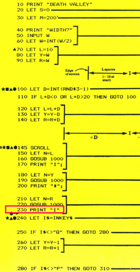
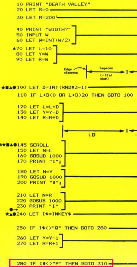
Anyway, on with the conversion! I have chosen to convert Death Valley from the Usborne book “Computer Spacegames” this time. It’s a shorter program but we will still encounter a few new techniques along the way.
Someone pointed out previously that I haven’t mentioned what computer or assembler I’m using (I have briefly mentioned this before in my Welcome post on the blog). In my case I’m using a Sharp MZ-80A which is a Z80 based computer. It’s rather nice to program for as the memory layout is very easy to get to grips with. There is 4K of ROM from memory address 0 and then there is 48K of RAM afterwards. The MZ-80A doesn’t come with any programming languages installed so there is no other software using the memory when you first switch the machine on. The 4K of ROM is called the Monitor. This is effectively a kernel program which provides a very small operating system that lets you load software from tape or disk or jump to memory locations using different single letter commands. The screen memory is 2K from memory address 53248 ($D000 in hexadecimal) of which only 1K can be displayed on screen at once (1000 bytes for a 40 column by 25 row screen).
Other 8-bit machines will have more complex memory maps and I advise researching these yourself before you attempt any machine code on them. Also, the Monitor (or kernel) provides a number of useful subroutines for e.g. reading the keyboard, printing to the screen. General use stuff like that. This is very helpful for the beginner and I will be using these subroutines in my conversions (I already used a few in my Searchlight conversion). Other 8-bit Z80 computers will have their own subroutines which you should use (refer to your manuals for those machines). I will always mention when I have had to use an in-built Monitor subroutine so that you can swap this out for one of your own if you’re on a different machine. When you become more familiar with machine code programming you will eventually want to circumvent these subroutines (as they are quite slow) and make your own to read the keyboard etc.
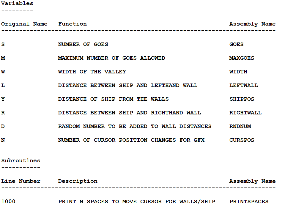
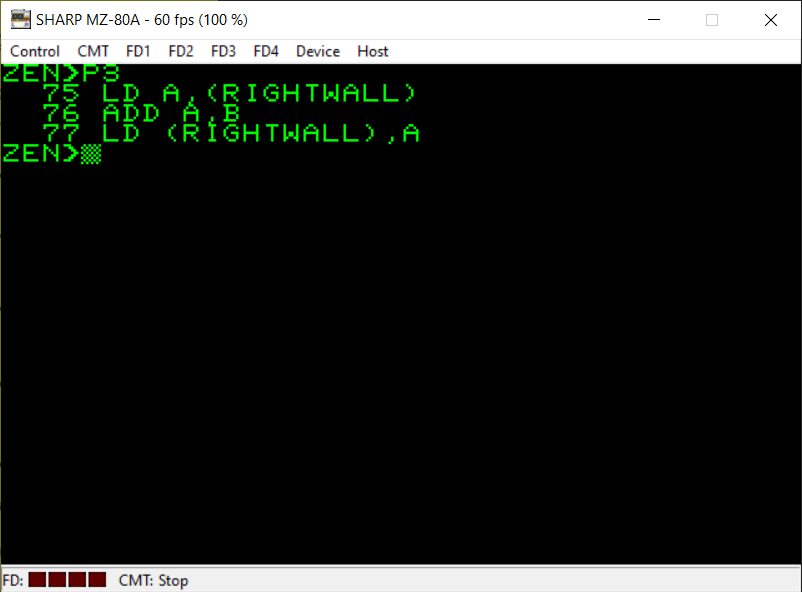
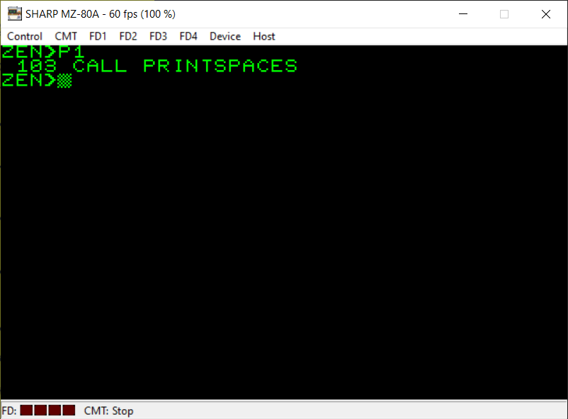
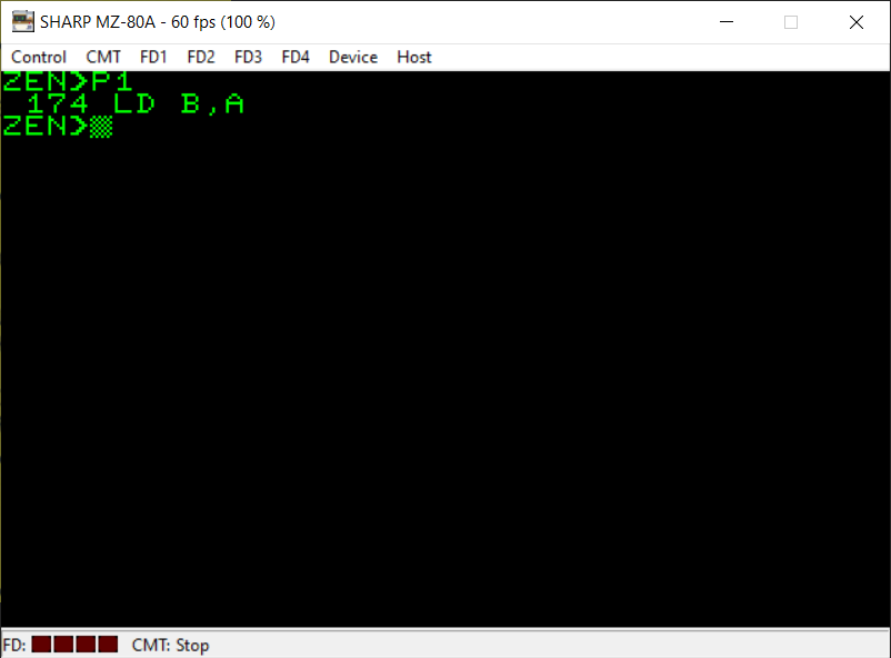
Lastly, I am using the assembler called Zen which was published by Avalon. As mentioned in the previous blog post for the Searchlight game my assembler doesn’t allow symbol names which are only a single character in length so I have gone through the listing for Death Valley and found all the variables. Then I have given them names in my assembler (please see the image above for details). I’ve done the same for any subroutines, in this case there’s only one subroutine for this game.
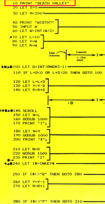
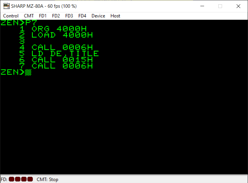
Okay, here’s the first line of the BASIC game converted to machine code and it’s a very simple one. We just want to PRINT the title of the game onto the screen.
The assembly code for this might seem a little complicated here for a simple task such as this but it is actually fairly straightforward. Ignore the first two instructions, these are not Z80 machine code instructions. These two commands (ORG and LOAD) are used in my assembler to tell it where to place the machine code program in memory. I’ve picked memory address $4000 (hex) as a fairly innocuous address as it’s far enough away from the memory addresses currently being used by my assembler software and also the actual assembly language program itself so that it won’t cause any problems (like overwriting the assembler!).
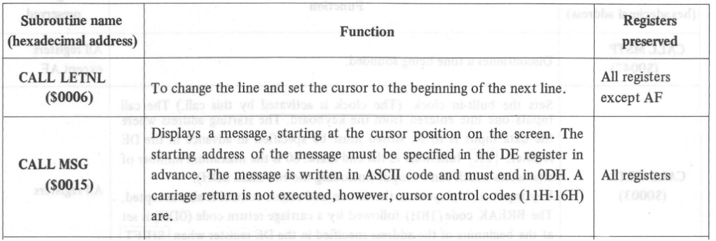
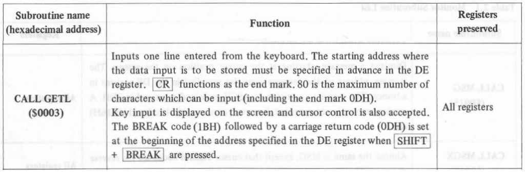
When you RUN a BASIC program the BASIC interpreter automatically places the cursor on a new line. This isn’t the case in machine code (at least for my computer) so I first CALL (equivalent of GOSUB) a subroutine which will place the cursor at the start of the next line. Then I put the memory address of my TITLE text (a string variable containing the text “DEATH VALLEY”) into the Z80 register pair called ‘DE’. Then I CALL the Monitor (or kernel) subroutine which PRINTs this text on the screen. This subroutine relies on the correct memory address for the string variable being present in the DE register pair before it is CALLed.
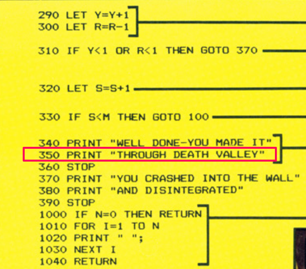
Finally, to properly provide an equivalent of the BASIC code we have to CALL yet another ‘new line’ subroutine to place the cursor at the beginning of the next line. As you will see from the original BASIC listing for Death Valley there is no semi-colon on the end of the PRINT statement in line 10 so this means we are not staying on the same line after the PRINT.
Details of the two Monitor subroutines I’m using are in the third screenshot above. For a different 8-bit machine please refer to your manual for that computer.
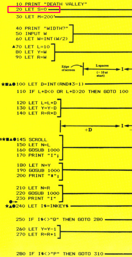

The next line of the BASIC listing simply assigns the value zero to the variable ‘S’. Referring to my notes, I have given this variable the symbol name ‘GOES’ in my assembler. Remember, in assembly language you can assign names to both variables and individual lines of the program (to be used with the branching instructions, JP, JR, CALL etc).
The LD instruction is used to assign a value to a register or memory address. In this instance, because we can’t directly access memory (with for instance LD (GOES),0 – that instruction doesn’t exist) we have to first pre-load the ‘A’ (accumulator) register with the value 0 and then the second LD instruction puts the value of A into the memory address referred to by the symbol name ‘GOES’.
You will see later on, towards the end of the assembly listing, how the relevant amount of memory for the variables is reserved.
I should also say at this point that I’m not giving a full description of how the BASIC listing for Death Valley works. That is covered in some detail in the Usborne book itself and I highly recommend working out how the BASIC listing works because then you’ll understand more easily how the assembly language listing works.


The variable M in the BASIC listing is used to contain the maximum number of goes the player needs to have before they’ve reached the end of the valley. I’ve given this variable the name ‘MAXGOES’ in my assembler. Again, we use the LD instruction to load the value 200 into the A register. Then we load the memory address referred to by the symbol name ‘MAXGOES’ with the contents of the A register.
You may remember from the Searchlight conversion that the brackets are important here. When we use brackets in an LD instruction (and in other instructions) we are referring to the contents of a memory location. We’re not referring to the memory location itself. If we didn’t have the brackets we’d simply be referring to a literal value and the CPU wouldn’t know we were talking about a memory address. It’d be like writing BASIC code such as “4000=3” which obviously is nonsensical. However POKE 4000,3 (basically what the brackets mean) makes sense.
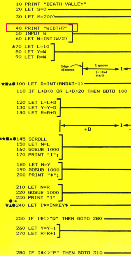
Line 40 of the BASIC listing is simply printing “WIDTH?” onto the screen. Here we are using the Monitor subroutines we’ve already encountered to both PRINT the message (held in DE) onto the screen and then also move the cursor onto a new line. DE is simply pre-loaded with the memory address where the CPU can find the relevant string of characters. We’ve given this string the symbol name ‘WIDTHMSG’ in this particular case. When the assembler creates your finished machine code it substitutes all these symbol names we’ve used with their actual memory addresses.
As a sidenote, the Z80 CPU uses what’s referred to as ‘Little Endian’ as a way of storing 16-bit numbers or memory address into memory. As each memory location can only hold a single 8-bit number any 16-bit numbers you want to use in your program must be stored in two 8-bit memory locations. These are stored in low-byte / high-byte order. For instance, if you had a 16-bit hexadecimal number $1234 and told the Z80 CPU to store this in memory it would store it as $34 in the first memory location and $12 in the second memory location.
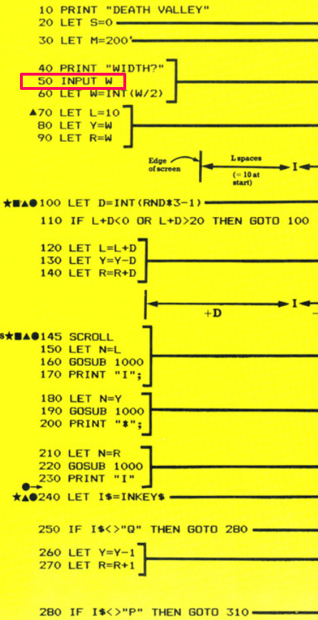
Well, this is interesting. Line 50 seems so simple and yet here we have what seems like a very long piece of assembly code as its equivalent 🙂 This is true and it is quite complicated but only because we want to attempt to validate a bit of what the user enters here.
The BASIC code is just asking the player to input a number. This is fine and, in fact, we could just use the first two assembly language commands shown in the above screenshot:
LD DE,WIDTH
CALL 0003H
You’ll see (from the third screenshot above) that there is a subroutine already provided by the Monitor at memory location 3 in ROM that will prompt the user for some input. Great! We just prime it with the memory location where we want it to store the characters entered by the user (a symbol name ‘WIDTH’ in this case) and CALL the subroutine. Job done! 🙂
Not quite! Yes that will work but there would be a variety of different problems depending on what the user does. BASIC already checks for these things, for instance it looks like we’re using a numeric variable in BASIC so any non-numeric characters entered would throw an error from BASIC. Also we really want sensible widths entered by the player (although the original Usborne listing doesn’t bother with this!)
There are lots of things we could check for. However, I’ve kept it ‘simple’ in this case and all I am doing here is checking to see if the user has entered only a single digit or whether there are two digits (the program ignores everything beyond the second character entered).
How does this happen? Well let’s find out:
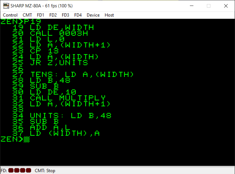
LD DE,WIDTH
CALL 0003H
We put the memory address ‘WIDTH’ into the DE register pair and CALL the Monitor subroutine which asks for keyboard input. This subroutine places all the characters entered into memory starting at the memory address held in DE. When the user has finished they hit the Enter key. This final keypress is also stored in memory as ASCII 13 ($0D in hex). This will help us to determine how many characters the player has entered.
LD L,0
Do not worry too much about this. We are just initalising the L register to zero because it’s going to be used later in our multiplication (if the player entered a two digit number). It will remain unchanged if there was no multiplication needed (i.e. the player entered a single digit width for the game). L is added onto A later to get the final width, as you’ll see.
LD A,(WIDTH+1)
CP 13
LD A,(WIDTH)
JR Z,UNITS
Here is where we check how many characters (or digits, hopefully) that the player has entered. We’re not checking whether they typed letters or numbers, as I say this could be improved a lot further but I’m keeping it simple for now.
All that happens here is we load the A register with the second character the player entered (WIDTH+1). The reason it’s WIDTH+1 is that refers to the next memory location along from the ‘WIDTH’ memory address. If the player only entered a single digit width then we are guaranteed that WIDTH+1 will be ASCII 13 for the carriage return they entered.
We compare A now with the value ’13’ (for ASCII 13). We set A now to the first character of the WIDTH string so it’s ready for later use. Then we have the ‘JR Z’ instruction which, if you remember from Searchlight, is like a conditional GOTO instruction. It will jump to the ‘UNITS’ label in the assembly code if the zero flag is set.
As a reminder, when a CP (or compare) instruction is used effectively what’s happening is that the value to the right of the comma in the instruction is being subtracted from the value (or register) on the left of the comma. So if A was 13 and we used CP 13 we are basically subtracting 13 from A (but leaving A’s contents unaltered) to see if they’re the same. If the answer is zero then As a reminder, when a CP (or compare) instruction is used effectively what’s happening is that the value to the right of the comma in the instruction is being subtracted from the value (or register) on the left of the comma. So if A was 13 and we used CP 13 we are basically subtracting 13 from A (but leaving A’s contents unaltered) to see if they’re the same. If the answer is zero then the Z (or zero) flag is set and the two values must therefore be the same.
‘JR Z’ provides us with a GOTO if the values were the same (the zero flag is set). It’s the machine code equivalent of ‘IF A=13 THEN GOTO…’
All we are doing is skipping straight to calculating the units (not the tens) for our width. If the character held at memory location WIDTH+1 was not 13 then we know the player has entered more than one digit and the ‘JR Z’ is not effective and we carry on to the next line of code.
TENS: LD A,(WIDTH)
LD B,48
SUB B
LD DE,10
CALL MULTIPLY
LD A,(WIDTH+1)
If we’ve reached this part of the code then we already know the player has entered more than one digit for the width (they may have entered multiple but we’re only going to use the first two and ignore anything else). So we know that whatever this digit is it will need to be multiplied by ten to get the correct width the player wants before we eventually move onto the ‘UNITS’ part of the code to add on the remaining second digit the player entered.
TENS: LD A,(WIDTH)
I’ve realised that I set LD A,(WIDTH) here unneccessarily as my first instruction. I already set it to this in the previous part of the code. I’m too far down the road with the screenshots etc to change this now 🙂 Don’t worry, you could ignore this instruction as A will already contain the value held at (WIDTH) when the CPU reaches this part.
LD B,48
SUB B
The subroutine we used which allows the player to enter characters at the keyboard only deals with strings. There is no difference really in machine code between strings and numeric variables. It’s your own program code which needs to deal with the different types of variables depending on what you’ve decided those variables will contain.
All that’s happening here is that we are subtracting 48 from the value currently held in the A register. The reason for this is that all the text entered by the player currently resides in memory as ASCII code. To get the real value of a digit (rather than its ASCII value) we need to subtract 48 from it. For example, the ASCII code for the digit 1 is 49. Once 48 is subtracted from 49 we’re left with the real value we’re after.
LD DE,10
CALL MULTIPLY
I am using the following Z80 multiplication routine here:
http://z80-heaven.wikidot.com/advanced-math#toc9
under the heading “DE_Times_A”.
If we reached this part of the program we know the player entered more than one digit for the width. I’m only catering for two digit maximum numbers. Therefore the first digit will always need to be multiplied by ten to get its true value.
The multiplication subroutine takes a number in A and multiplies it by the value in DE. The output is held in three registers: A, H and L. So L will hold the lowest part of the resultant multiplication. As we’re only really going to be dealing with sensible widths (nothing greater than the size of the screen for instance – 40 characters) then I only really need to use the result from the L register and can safely ignore the H and the A registers.
LD A,(WIDTH+1)
The final instruction of this part of the code simply moves A onwards to the next digit that the player entered (again we’re only doing this because we know that if we’re in this part of the program then the player definitely entered more than one digit).
UNITS: LD B,48
SUB B
ADD A,L
LD (WIDTH),A
Finally this part simply takes the value in A and subtracts 48 from it to get its real value (rather than ASCII value). We can reach this part of the program in two ways, either directly via the “CP 13 / JR Z” instruction from the first part of this section or via the section that calculates the ‘tens’ via multiplication. Either way we know that A now contains the next (or only – depending on what the player entered) digit we want to work on.
We add the contents of L to A. This is either zero or, if we had to carry out the multiplication, the ‘tens’ digit the player entered.
Finally we store the end result into the memory location with the symbol name ‘WIDTH’. This is the same ‘WIDTH’ we used as a storage location for the characters the player has entered. It doesn’t really matter, we overwrite what they entered with the real values now. It isn’t important as we won’t be using what the player entered again in the program so this ASCII data can just be overwritten / erased without consequence.
Again, if you’re using a different 8-bit machine then refer to your own manual for an equivalent kernel subroutine for inputting characters from the keyboard.

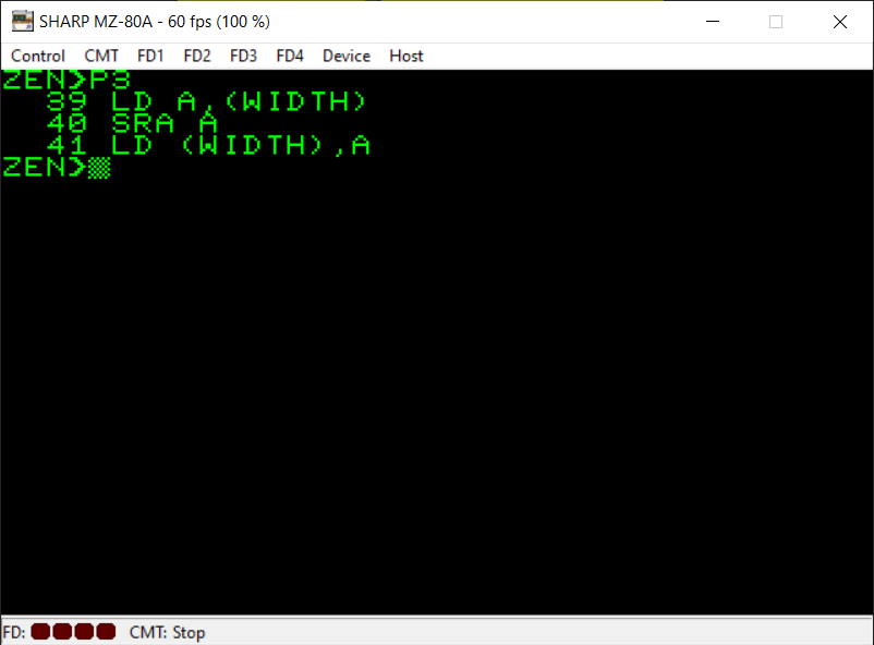
All we want to achieve with this BASIC line of code is divide the width in two and store it back into itself.
Luckily the Z80 instruction ‘SRA’ can help us out here. What it does is shift all the bits in an 8-bit byte to the right. This has the effect of dividing the number in the specified register by 2.
As an example, take the decimal number 78. In binary this is:
01001110
If this value was stored in the A register and we performed the ‘SRA A’ instruction then A would end up with the bits moved to the right, like this:
00100111
Which in decimal is 39. That’s 78 divided by 2 🙂
It seems like magic but it really does work. I won’t go further into it because naturally you’ll wonder what happens when the bit at the right-most position moves right and ‘falls off’ into a void but as this is just for beginners we’ll keep it simple and will settle for the fact that, in most cases, this will work for us.
Oh and there is an equivalent instruction we can use if we want to multiply by 2 which is “SLA”.
So as you can see from the assembly code, we put the value currently held in the memory location referred to by ‘WIDTH’ into the A register. We shift its bits to the right by one position and we put the result back into the memory location referred to by ‘WIDTH’.
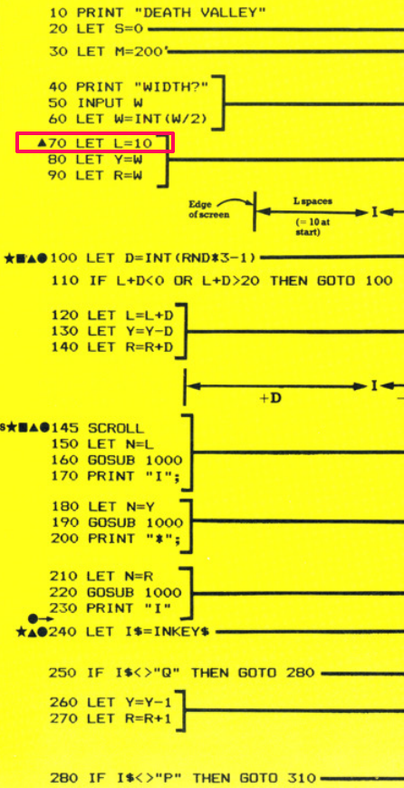
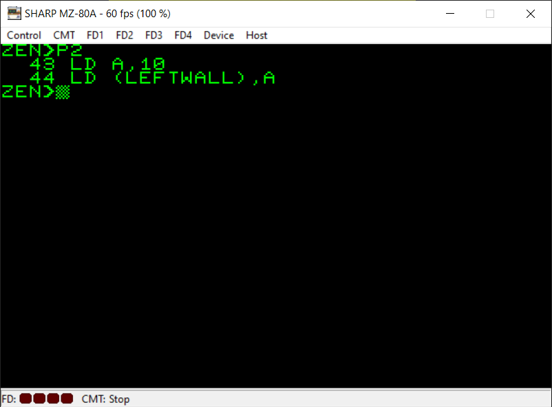
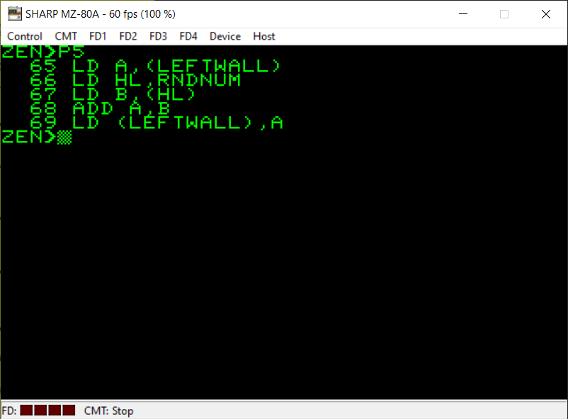
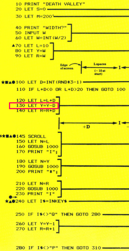
Again, very simple. The BASIC line puts the value 10 into the variable L. I’ve chosen the symbol name ‘LEFTWALL’ for this variable as it is used to determine the spacing for the left-hand wall in the game.


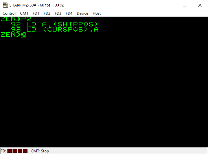
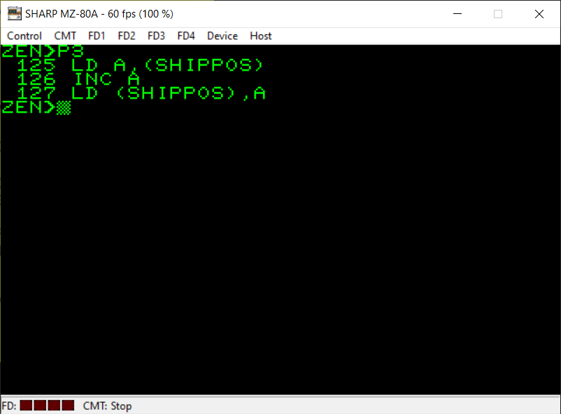
The BASIC listing wants to assign the width held in the W variable to the Y variable. So we load the value held at the ‘WIDTH’ memory location into the A register and then we load the memory location referred to by ‘SHIPPOS’ with the value currently held in the A register.
Again, as a sidenote, there is no instruction that would let us access the memory directly with a value instead of a register (i.e. you can’t put LD (SHIPPOS),(WIDTH) – that format of instruction is not available on the Z80).
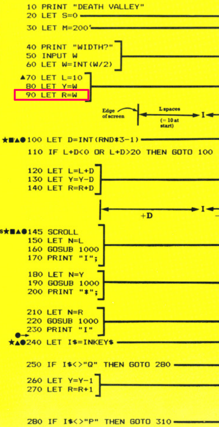
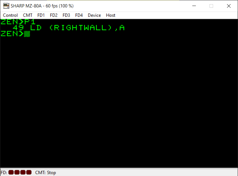
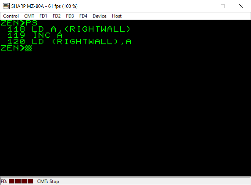
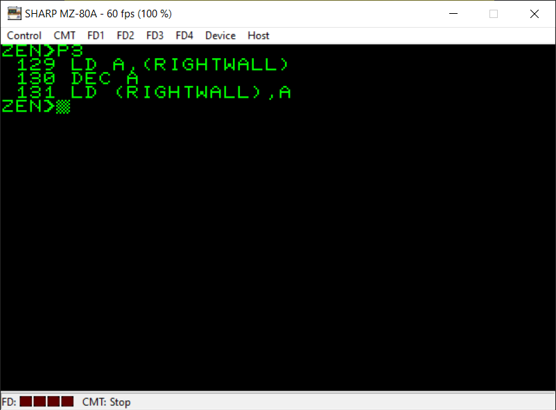
Again in BASIC the width needs to also be stored in the R variable. Referring to my notes I am using the symbol name ‘RIGHTWALL’ to represent the R variable. As A hasn’t changed its value from the last couple of instructions we can simply load the memory location referred to by ‘RIGHTWALL’ with the current value of A.
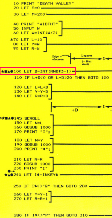
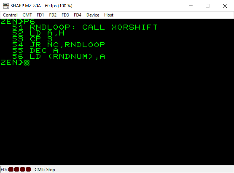
This part of the BASIC program generates a random number between 0 and 2 and then subtracts 1 from it. This results in numbers between -1 and 1 to help alter the position of the walls on the screen.
For the assembly language equivalent, I have used the random number subroutine shown on this website:
https://wikiti.brandonw.net/index.php?title=Z80_Routines:Math:Random
under the heading ‘Xorshift’. This seems to provide better random numbers than the routine I used for Searchlight.
So, firstly we CALL this subroutine which outputs a random number into the HL register pair. We can just use the numbers in H as these will be just as random. Now we need to make sure the random numbers are within the range we want (0 to 2):
LD A,H
CP 3
JR NC,RNDLOOP
We’ve created a loop here where if the number is not in the range we want we loop back to the ‘RNDLOOP’ label which CALLs for a new random number, until we get a number within the range we want.
This is achieved with the ‘CP 3’ instruction. We compare the random number in the A register with 3. So this will compare the two values by subtracting 3 from the value in the A register. If 3 is larger than the value in A then the carry flag will be set. If there isn’t a carry generated by this subtraction then the random number was too big (i.e. no carry was created when 3 was subtracted from A).
OK, by this point we now have a number between 0 and 2 stored in the A register. To also subtract 1 from this random number, we simply use the ‘DEC’ instruction. In this case ‘DEC A’ which subtracts 1 from the value currently in the A register.
You may remember from my Searchlight conversion that the 8-bit registers can only store numbers from 0 to 255. What will happen when we subtract 1 from the A register when it has the value 0 in it? Well, effectively we end up with 255 ($FF in hex) in the A register. This is actually okay though and will still represent -1 as you will see shortly 🙂
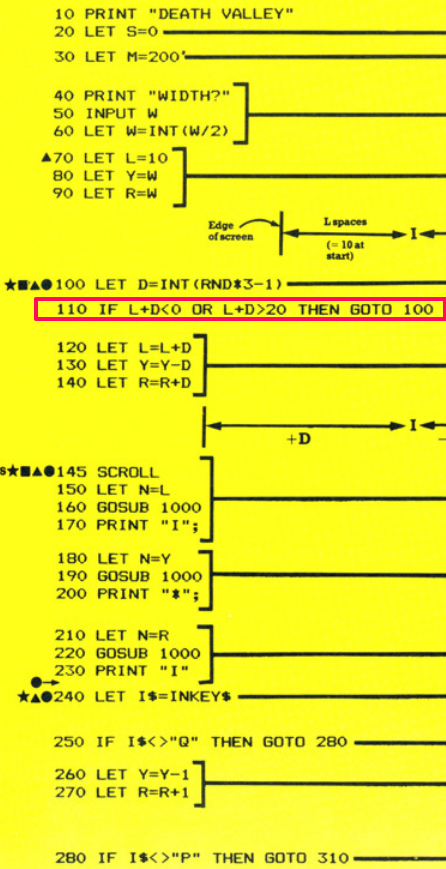

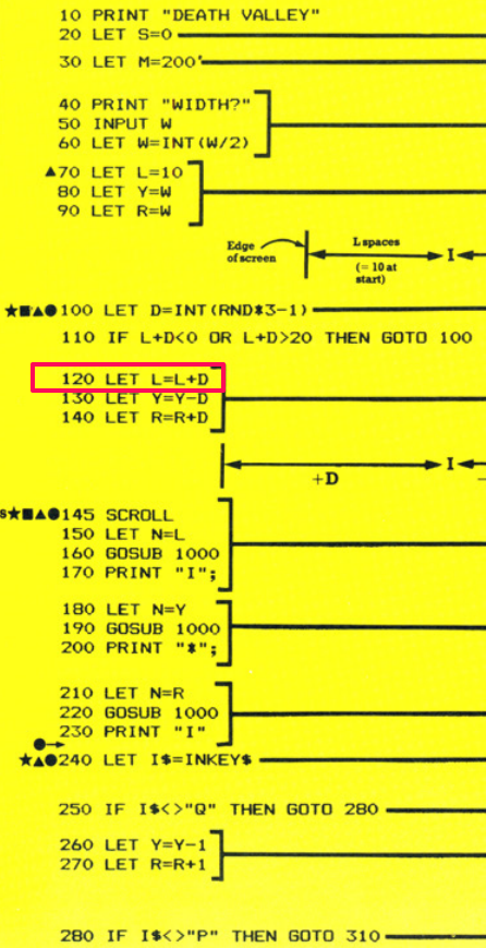
I had to think about this part of the BASIC program for a while before settling on a much easier way to represent it in machine code. As a reminder (so you don’t have to flip back to the screenshot) the BASIC line is as follows:
IF L+D<0 OR L+D>20 THEN GOTO 100
All this is doing is checking to ensure that L+D isn’t too big or too small that the gameplay area will print incorrectly on the screen.
There are two expressions which BASIC is evaluating for this, checking whether L+D is less than zero or that it’s greater than 20.
I realised that this can be achieved with just one simple comparison in machine code. The first three lines of the machine code store the value of ‘LEFTWALL’ in the A register and the random number we created in the B register.
We add them together with ‘ADD A,B’ (the result is stored in A) and then we compare (using ‘CP’) the value in A with 20. As you know by now, the comparison is really a subtraction. The value 20 will be subtracted from the value in A (but won’t alter A at all).
Well, if A was -1 then really its value is 255 as explained in the previous notes for line 100. This is actually very useful for us because with one simple subtraction of 20 from A we can determine both whether the value is greater than 20 and less than zero.
Both of those situations will result in no carry. To better explain this let’s take two examples:
A=30
Well, 30-20 doesn’t result in a carry because A is bigger.
A=-1 actually will be A=255
Again, 255-20 doesn’t result in a carry.
With one simple comparison we have achieved what the BASIC listing had to do in two separate comparisons. It takes longer in BASIC because BASIC is essentially more user friendly and feature-rich. BASIC is designed to know the difference between -1 and 255 for instance.
But as beginners, we’re not going to worry about how negative numbers are represented in machine code. For now, we will just work with the fact that only positive numbers between 0 and 255 can be stored in an 8-bit register.
With the last instruction in this section of our assembly program we simply jump back to generating a new random number if there wasn’t a carry generated by our ‘CP 20’ instruction.
Hopefully you’re familiar enough with the LD instructions and the ADD instructions by now that this should be fairly straightforward for you 🙂
I will just note that, although we can load a value directly from a memory location into the A register we cannot actually do this for the B register. There isn’t an instruction like that for the B register. So there’s an extra step of putting the memory location we want to fetch the value from into the HL register pair and then using ‘LD B,(HL)’ to put the value at the memory location referred to in HL into B.
It’s easier for the A register as this is the accumulator register which is used in many mathematical and comparison instructions either implicitly or explicitly. The B register is more general purpose (but is often used for loop counters) and there are less instructions to access memory directly for this register.

There are slightly less instructions used here as we still have the correct value in the B register left over from the previous section of code. This hasn’t been altered at all so we don’t need to put this value into the B register again. The ‘SUB B’ instruction simply subtracts the value in B from the value in A. The answer is stored in A.
This is one of the occasions where the A register is implicitly specified. We don’t have to put ‘SUB A,B’. The instruction is simply SUB B because the A register is implied. I would strongly suggest, again, getting hold of a copy of Rodnay Zacks’s “Programming the Z80” book so you can see the types of instructions available to you on the Z80. Another good resource is this website:
Finally in this section we store the value held in the A register back into the memory location referred to by the symbol name “SHIPPOS”.

And again, you should be fairly familiar with this instructions now so I won’t spend extra characters describing what’s happening here 🙂
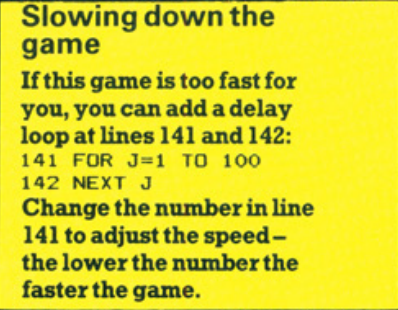

Usborne suggest slowing the game down with a delay loop if it is too fast to play. This was certainly the case when I first tested my machine code version of the game. Surprisingly, it was still playable though (just!). This is due to using Monitor subroutines for PRINTing as opposed to making everything myself from scratch. If I had done that then there would be no chance for the player.
Even so, I still wanted to slow the game down. All I’ve done is create a subroutine which checks for the vertical blank of the screen display. I’ve then set up a loop via the B register. I’m going to wait for 8 vertical blanks by storing 8 in the B register and using the ‘DJNZ’ instruction to decrement (decrease) B by 1 for each iteration of the loop and jump back to the beginning of the loop if B isn’t zero.
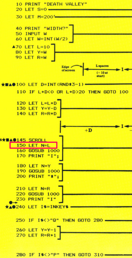

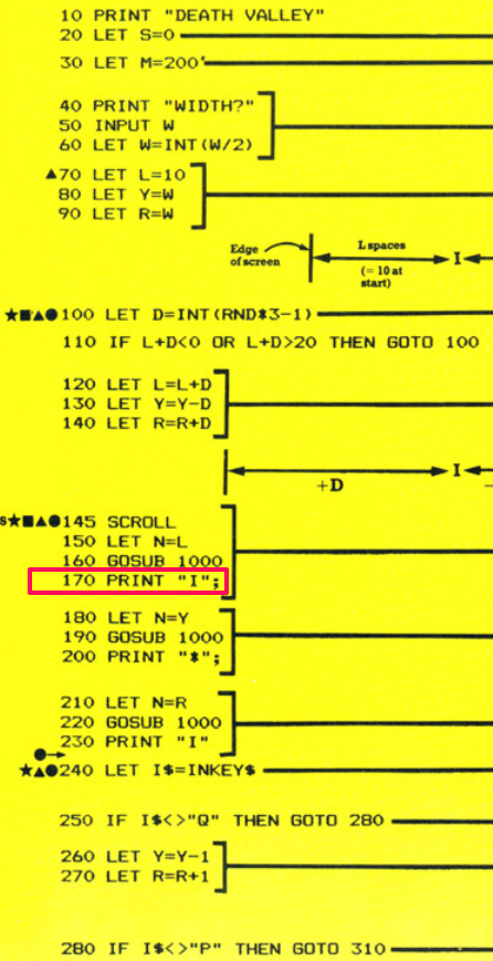
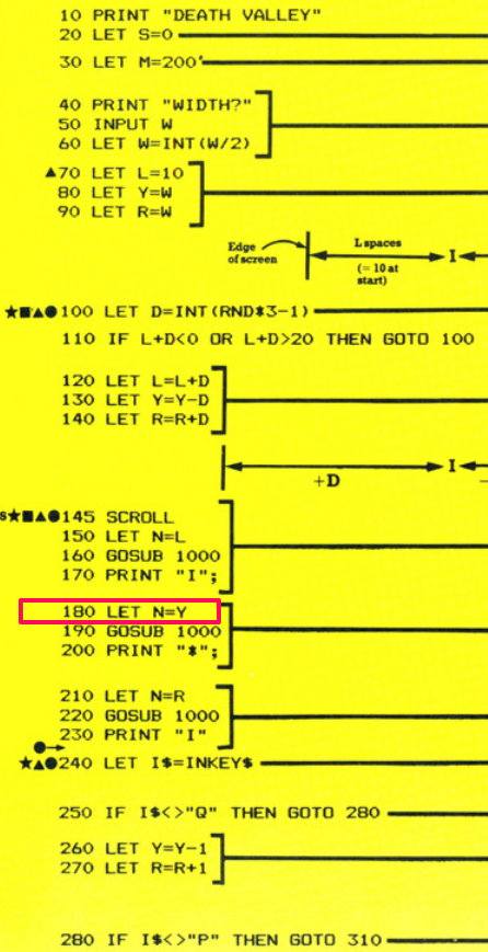
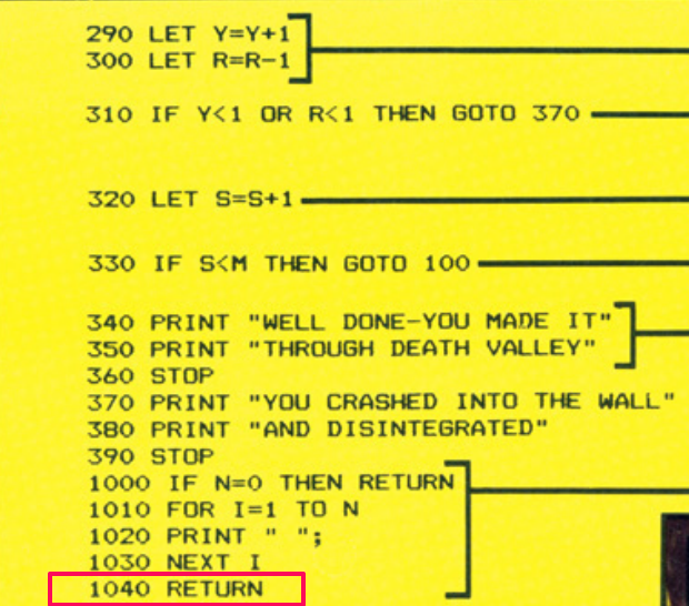
The variable N in the BASIC listing is used in a subroutine at line 1000 to print a specific number of spaces at the cursor position. The BASIC listing primes this variable with the value held in the variable L. Going back to my initial notes, I’ve given the L variable the symbol name ‘CURSPOS’ in my assembler.
I’ve covered the LD instruction a lot so I’m sure you’re used to it already but we first put the value held at the memory location referred to by ‘LEFTWALL’ into the A register. Then we put this value (held in A) into the memory location referred to by the symbol name ‘CURSPOS’.
There isn’t a way to do it in one line of code as there is no instruction to do this (no ‘LD (CURSPOS),(LEFTWALL)’ instruction exists). So we have to take two steps to achieve this single line of BASIC code.
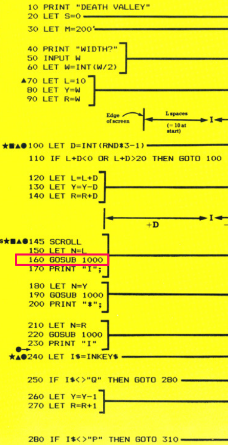
The equivalent of the BASIC ‘GOSUB’ command is the ‘CALL’ instruction. As shown in my initial notes I’ve given the subroutine at line 1000 the label ‘PRINTSPACES’. So you can see this part of the assembly code is pretty self-explanatory 🙂
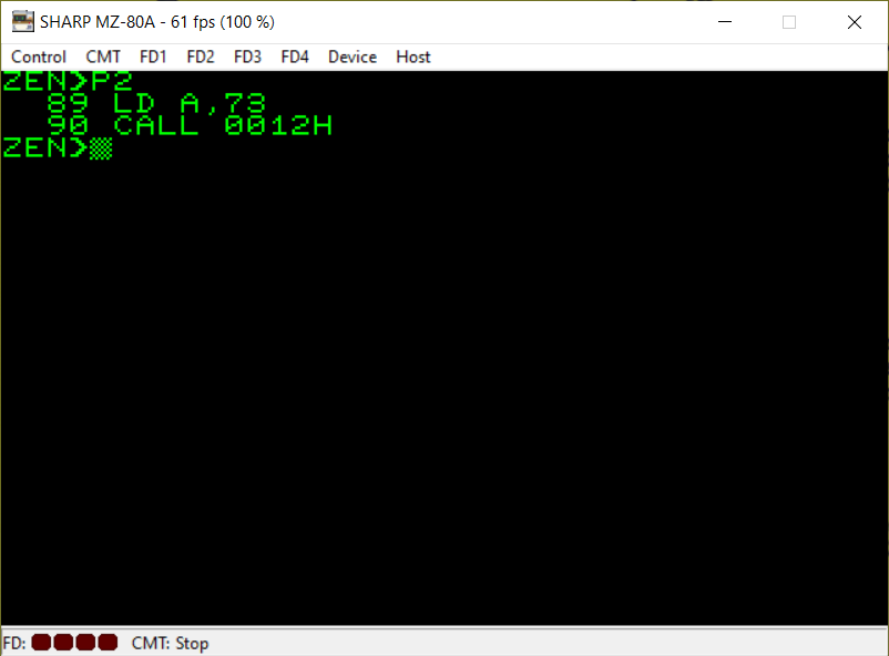
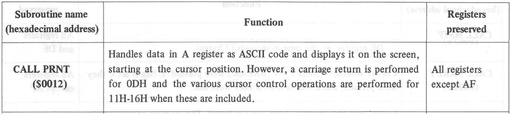
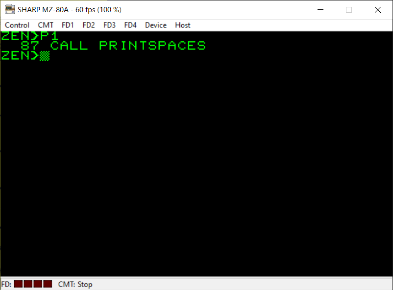
At this point in the game a part of the wall is drawn on the screen. It’s actually just the letter ‘I’ which is ASCII code 73. If you look at the third screenshot above you’ll see which Monitor subroutine I’m referencing here in my assembly code. First we load the value 73 (for ASCII ‘I’) into the A register and then we CALL the relevant subroutine which will PRINT the single ASCII character on the screen.
As usual when it comes to the Monitor subroutines for the Sharp MZ machine, you will need to refer to your own machine’s manual or documentation to find an equivalent bit of code here if you’re using a different 8-bit computer.
I will leave it to you to work out what’s going on here 🙂 Hopefully you’re familiar enough with the LD instruction and the meaning of the brackets now to understand this portion of the code.
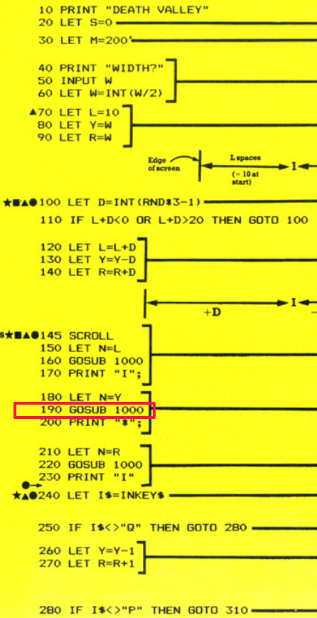

Here we are again with another GOSUB which translates precisely to the ‘CALL’ instruction 🙂 The label “PRINTSPACES” will be translated to a real memory address automatically by the assembler when you actually assemble your code.
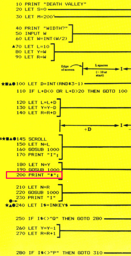

On this occasion we want to print an asterisk on the screen which represents the player’s ship. The ASCII code for an asterisk is 42. So we put the value 42 into the A register and then CALL the relevant Monitor subroutine which will print the contents of the A register on the screen at the current cursor position.
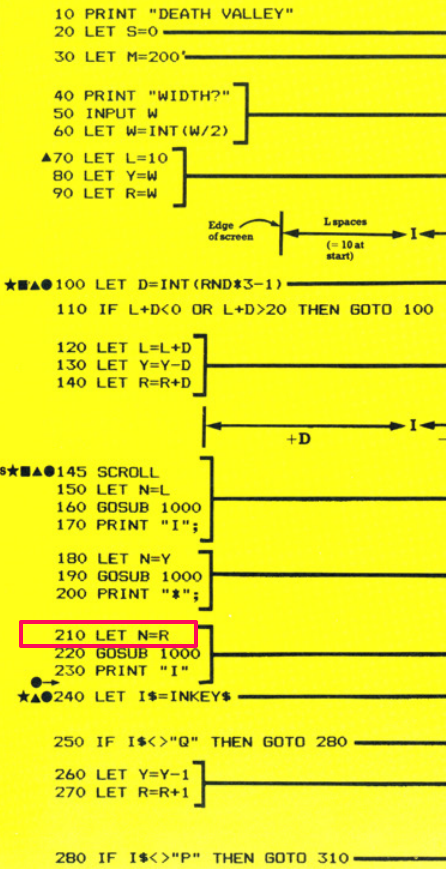
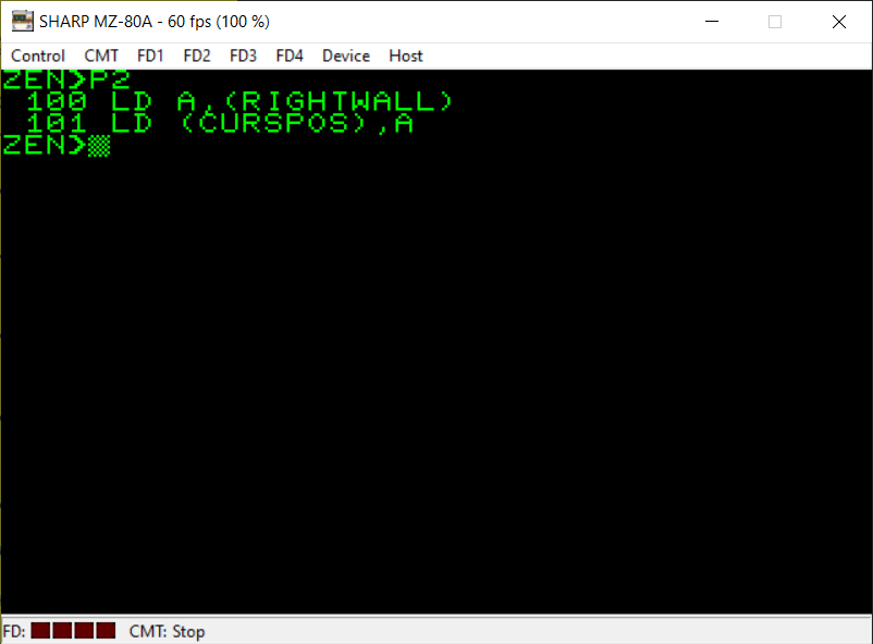
This part of the Usborne game is similar to that of line 180. Effectively, we are working out how many spaces to print on the screen to cover some of the width of the play area and calling the subroutine with this value. Here we make sure the memory location referred to by its symbol name as ‘CURSPOS’ is loaded with the value in A (which has been loaded already with the value of ‘RIGHTWALL’). The symbol name ‘CURSPOS’ is used in the PRINTSPACES subroutine later.
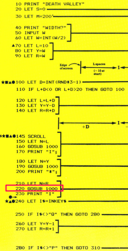
Off we go again to the subroutine which prints spaces on the screen 🙂

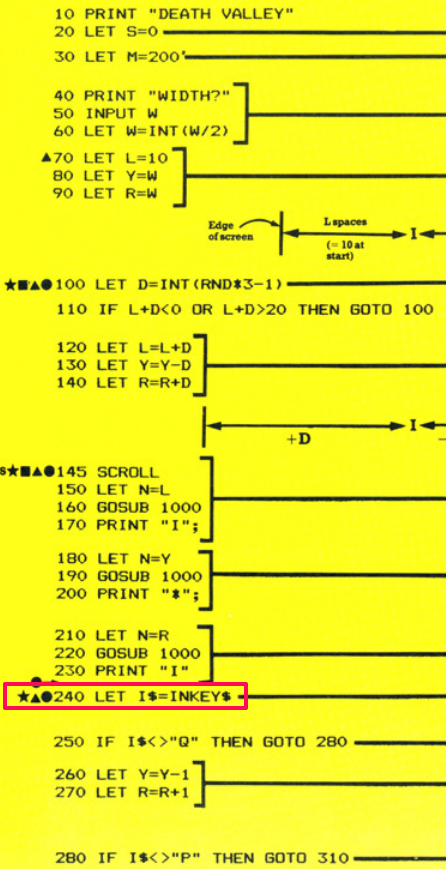
The right-hand wall is now printed on the screen at the current cursor position. You’ll notice that after loading the ASCII value for the letter ‘I’ into the A register and CALLing the subroutine to PRINT it on the screen we also CALL the subroutine to move the cursor onto a new line. This is because in the BASIC listing on line 230 there is no semi-colon on the end of the PRINT statement so we have to ensure we make the same process happen in machine code.

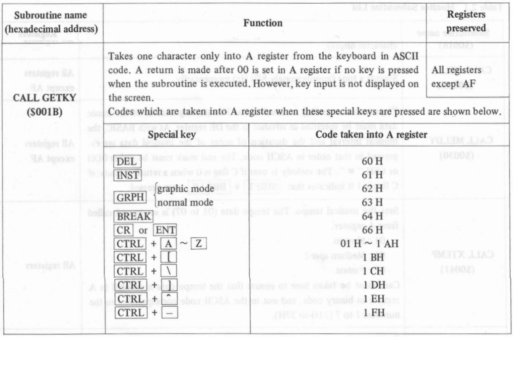
We’re going to use another Monitor subroutine here. This one takes keyboard input from the user and places the key they pressed into the A register. The third screenshot above will explain this as well. You simply CALL this subroutine and if a key was pressed then its ASCII value will be stored in the A register.
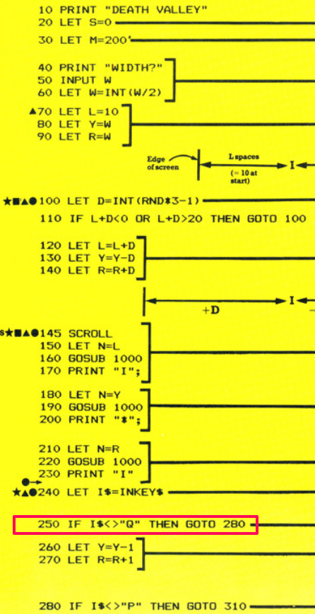

The first instruction here is ‘CP’ which will compare the value specified with the current value stored in the A register. We’re looking for the ASCII code 81 (the letter ‘Q’) to see if it’s been pressed. The following instruction is a jump (GOTO equivalent) instruction which checks if the zero flag is not set (the ‘NZ’ part of ‘JR NZ’). As explained previously, when you use the CP compare instruction it actually performs a subtraction of the value specified from the A register. If the result was zero then the two values are the same and the zero flag (in the flag register) is set. If not then the zero flag wasn’t set. Therefore if the Q key hasn’t been pressed the zero flag won’t be set and we then jump past the next few instructions to the label called ‘CHECKP’.
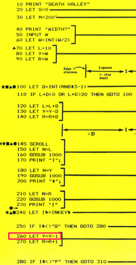
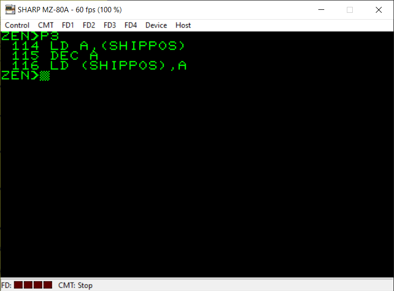
To achieve Y=Y-1 we first load the value stored at the memory address ‘SHIPPOS’ into the A register. We then use the ‘DEC A’ instruction to decrement A (decrease its value by 1). Then we store the new value held in A back into the memory address referred to with the symbol name ‘SHIPPOS’.
If you remember from the Searchlight conversion I mentioned that you have to manage the memory yourself when writing machine code programs. You need to reserve some memory for all of your variables (unless you’re writing an extremely short program which will only use the Z80 CPU’s registers). In BASIC this is all handled for you. When you define a variable in your BASIC program the BASIC interpreter will reserve some memory for it and you don’t need to worry about any of this background process. With machine code, you are in complete control of everything. You will see later in the conversion where and how I have reserved the memory for each of my variables.
A very similar process to the previous BASIC line but in this one we are using the ‘INC A’ instruction to increment the value stored in the A register by 1.

Now we’re checking to see if the ‘P’ key was pressed by the user (back when we checked for keyboard input a few lines ago). The A register will still contain the keyboard input if the ‘Q’ key wasn’t pressed and the ‘JR NZ,CHECKP’ was executed therefore it’ll be ready to be tested here with the ‘CP 80’ instruction to find out if the ASCII code for ‘P’ was pressed. If the zero flag wasn’t set (which we test for in the ‘JR NZ’ instruction) then the ‘P’ key wasn’t pressed and we jump onwards in the code to the ‘CHECKCRASH’ label where we will check if the player has crashed into a wall.

We’re in familiar territory here 🙂 All fairly standard machine code.
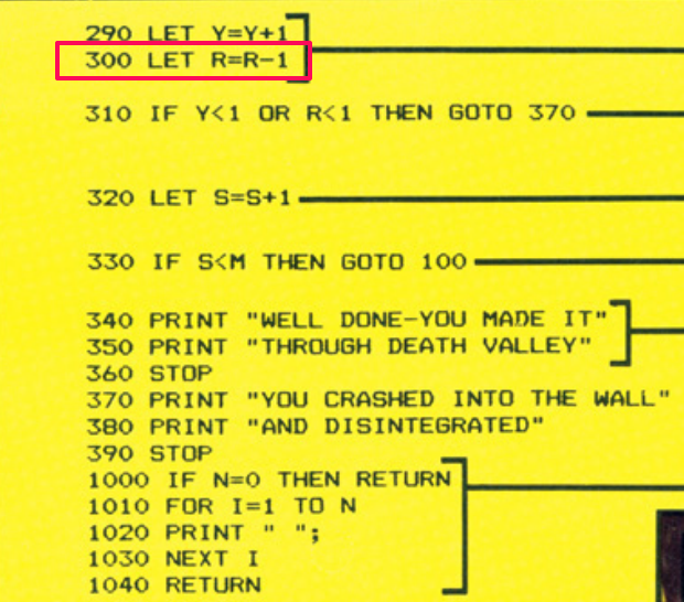
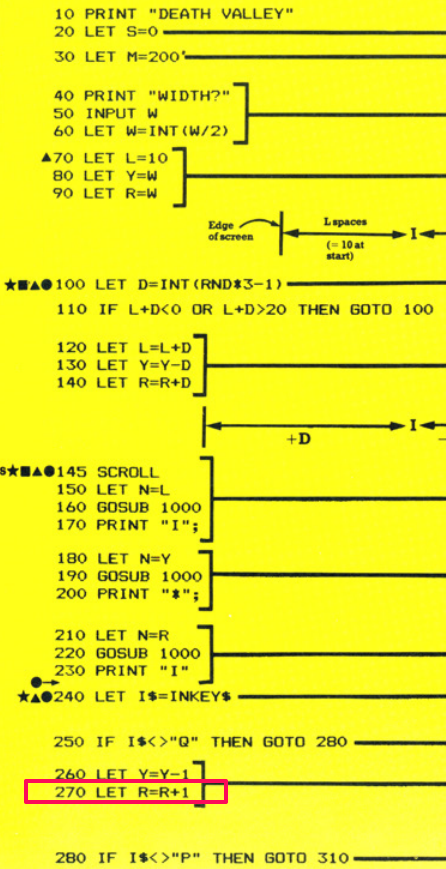
Again, very familiar code which is carrying out a quite simple process as the equivalent of ‘LET R=R-1’.
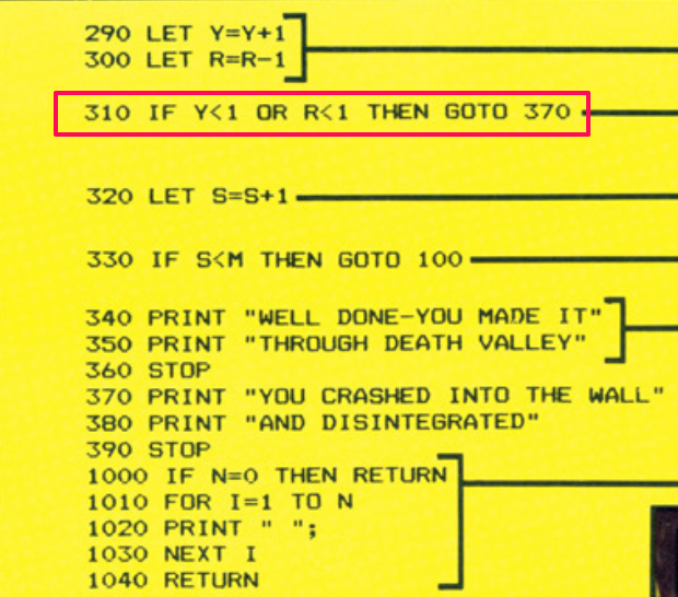
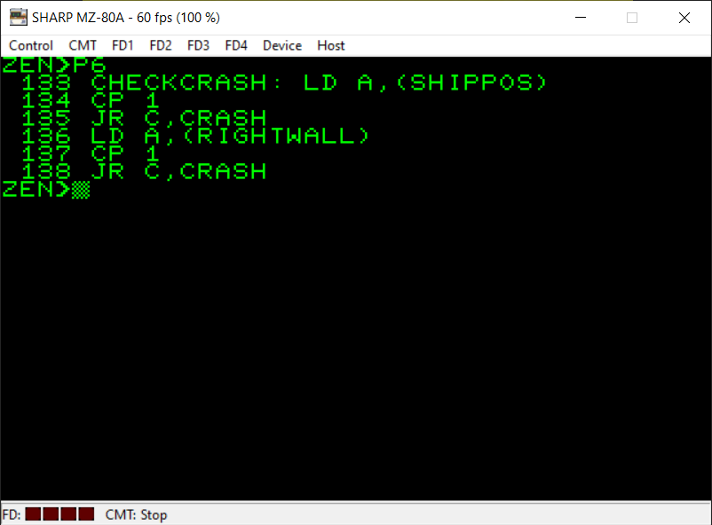
This part of the BASIC code is checking to see if either the current position on the screen of the player’s ship is less than 1 (which would mean the ship has definitely crashed into the left-hand wall) or the current position of the right-wall is less than 1 which would mean the distance between the ship and the right-hand wall is too small and the player has crashed into the right-wall.
This is achieved by putting the relevant values into the A register and carrying out a comparison (with the ‘CP’) instruction. The value we’re comparing is subtracted from the value held currently in the A register.
If the value to be subtracted is bigger than the value currently in the A register then this will result in a carry and the carry flag in the flag register will be set. Therefore we use ‘JR C’ to jump to the part of the code labelled ‘CRASH’ if the carry flag is set.
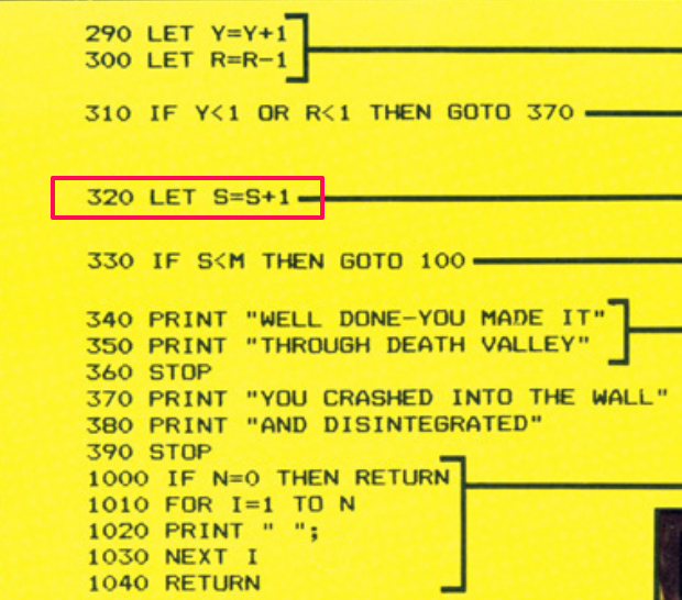
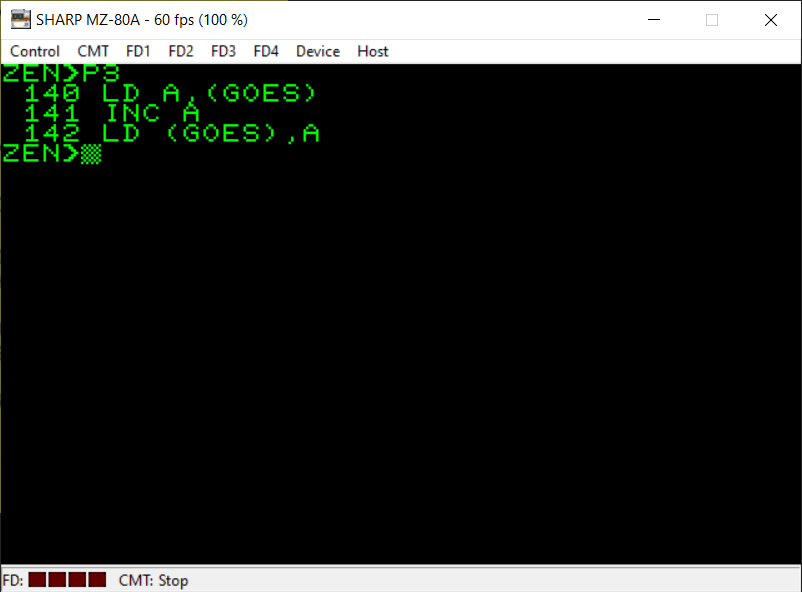
We’re simply increasing the number of goes the player has taken by 1 here. We put the value currently in the memory location referred to by the symbol name ‘GOES’ into the A register. Increase it by 1 using the ‘INC A’ instruction and put this value back into the ‘GOES’ memory location.

You’re probably familiar with most of these instructions already but it’s good to show here that, although usually we have been comparing values with A using the ‘CP’ instruction in this particular case you can see that we can also compare a specified register with the A register. Here we’re comparing the value in the B register with A. This is equiavalent to “A-B”. B is subtracted from A (but A’s value isn’t changed during this process) and the flag register is set as appropriately (i.e. if there was a carry or the answer to this subtraction was zero).
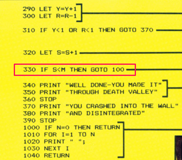
Here, if the maximum number of goes the player can take (in the B register) is still larger than the number of goes they’ve actually taken (in the A register) then this will result in a carry (the carry flag will be set) so we jump if this is the case back to the start of the main game loop (the section beginning ‘RNDLOOP’).
We’re using ‘JP’ here instead of ‘JR’ because the memory location we want to go back to is too far away for us to be able to use the two byte ‘JR’ instruction. ‘JP’ lets us specify a precise memory location to jump to (but does take up three bytes in memory – one byte for the JP instruction and two bytes to represent the specific memory address). ‘JR’ is a relative jump either 127 bytes backward from the current part of your program or 128 bytes forwards. We need to jump further back in the program than this so we must use ‘JP’.
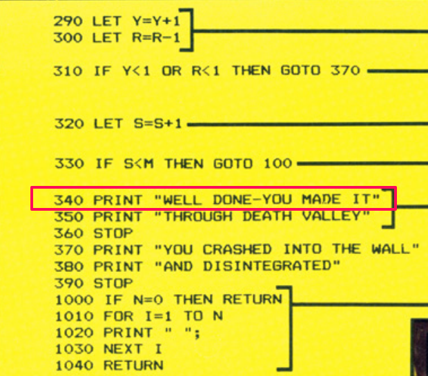
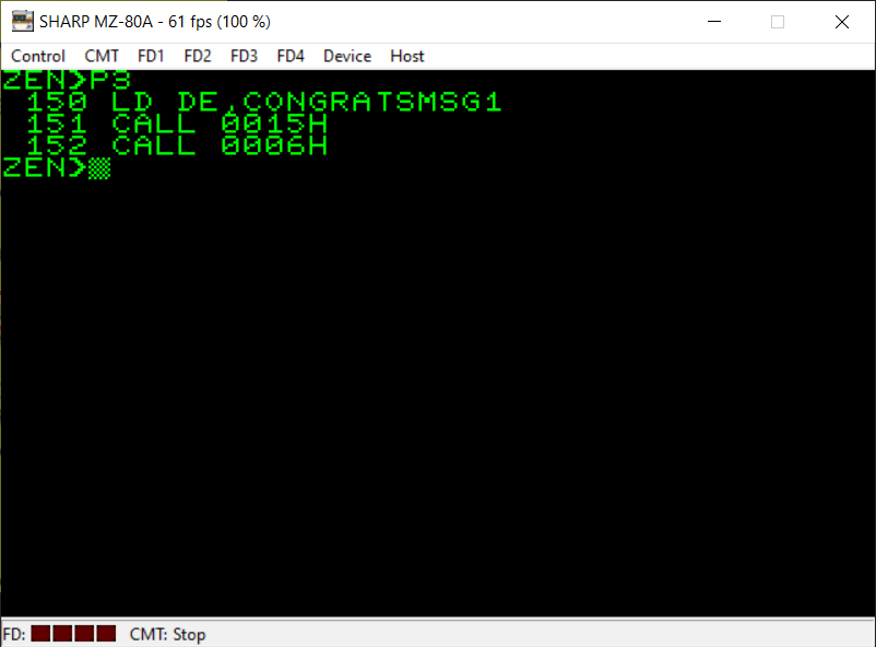
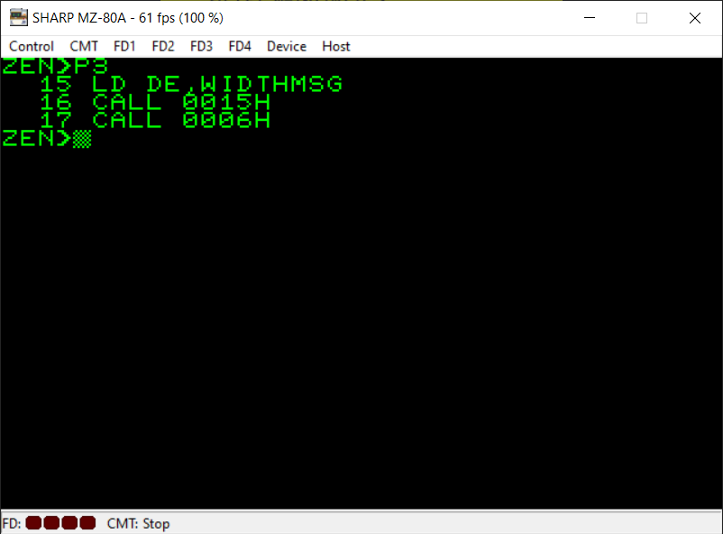
The next few lines of code are simply concerned with printing the relevant messages on the screen for the player. The subroutine at memory address $0015 will print the message whose memory address is stored in the DE register. We also CALL the subroutine at $0006 which moves the cursor to a new line as there is no semi-colon on the end of the PRINT instruction in the BASIC version.
Again, please find relevant replacement subroutines for any Monitor subroutines I have used on my MZ-80A.

Next line of text for the player is PRINTed on the screen 🙂
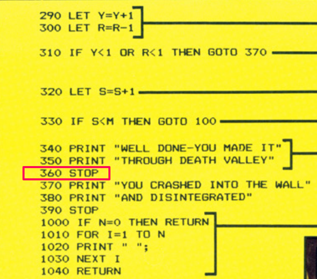
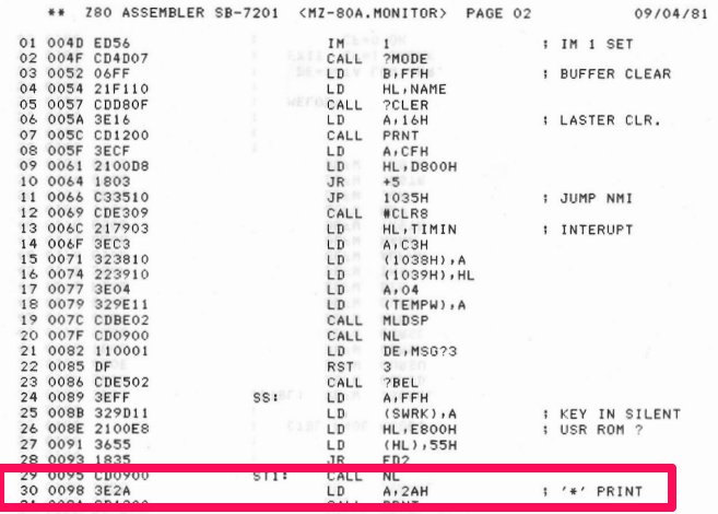
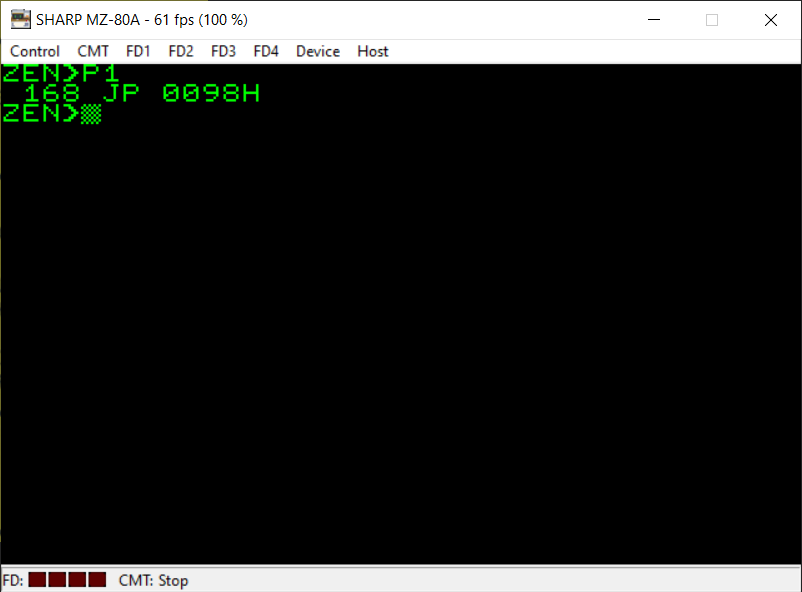
The message to the player has been PRINTed on the screen and the BASIC listing simply uses the ‘STOP’ command to bring the program to an end. To represent this in machine code I’ve basically jumped straight to the beginning of the Monitor. You can see from the third screenshot above a disassembly listing which shows that specific area of the ROM. It simply prints an asterisk on the screen and waits for keyboard input.
When you switch on the MZ-80A the first thing you are presented with is a prompt from the Monitor where you can load programs from tape or you can jump to a memory location if you wish. This is because the MZ-80A has no software, language or operating system in memory when it’s first turned on.
I’ve simply put the user back at this prompt. The game can be restarted with the Monitor command ‘J4000’ as we have chosen to store our game at memory location $4000 (hex).
On a different 8-bit machine you will need to make a different choice on what action to take here.


If we’ve reached this part of the code then the player has crashed into a wall. We display the first part of the message to the player on the screen and carry out a new line.
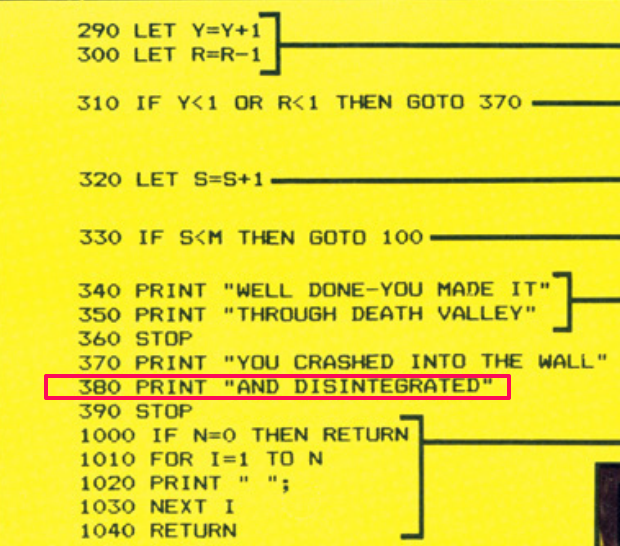

And the second line of text for the player is displayed on the screen.
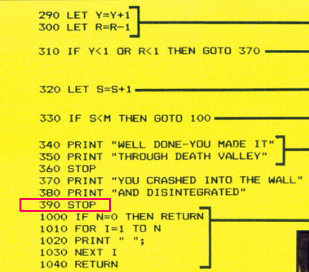
Again, to represent the BASIC ‘STOP’ command we just jump back to the part of the Monitor ROM which waits for user input.

These are familiar commands already now except for the ‘RET Z’ instruction. We’ve already encountered ‘RET’ on its own but here we include a test for the zero flag. We’ve seen the Z flag used in conjunction with ‘JR’ and ‘JP’ before but the ‘RET Z’ instruction is very similar to the BASIC ‘RETURN’ command except it will only RETURN from this subroutine if the zero flag is set. So if the A register is set to zero then we will RET back from where this subroutine was CALLed.
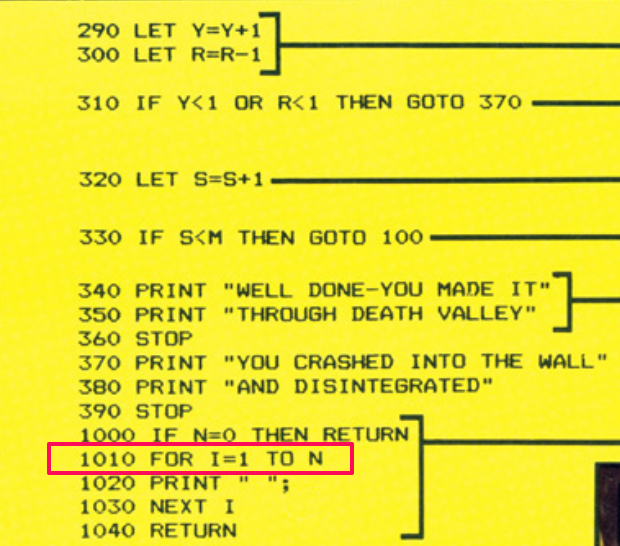
Line 1010 in the BASIC listing is setting up a ‘FOR’ loop. In Z80 machine code there is a really useful feature which we can view as the equivalent of ‘FOR..NEXT’. It involves the B register and the DJNZ instruction. We’ve encountered this before in the Searchlight conversion but to explain again, the B register is loaded with the number of iterations of the loop we want and instead of ‘NEXT B’ we use DJNZ which combines a decrement of the value stored in B with a test to see if it’s reached zero or not and jumps back to the start of the loop if it hasn’t. So here we already have the value we want in the A register so we just load it straight into the B register with ‘LD B,A’ ready for our loop to begin.

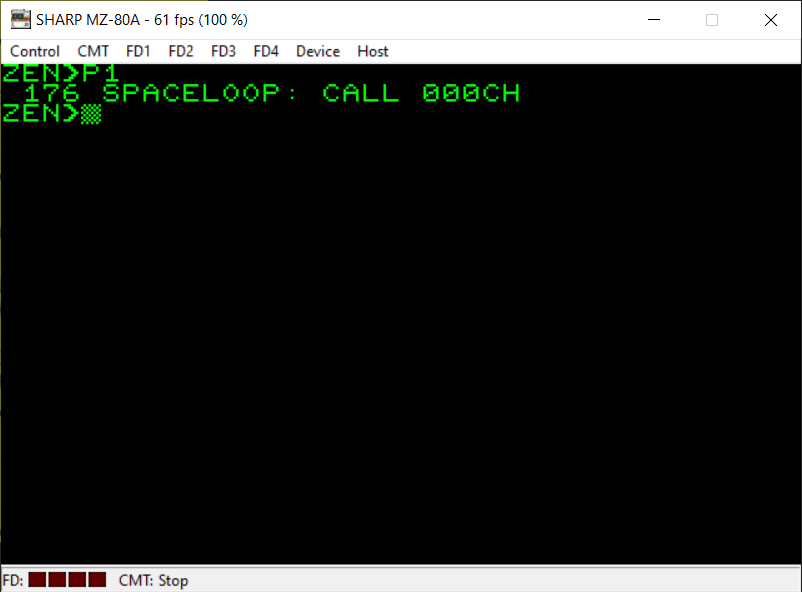
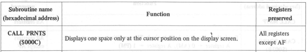
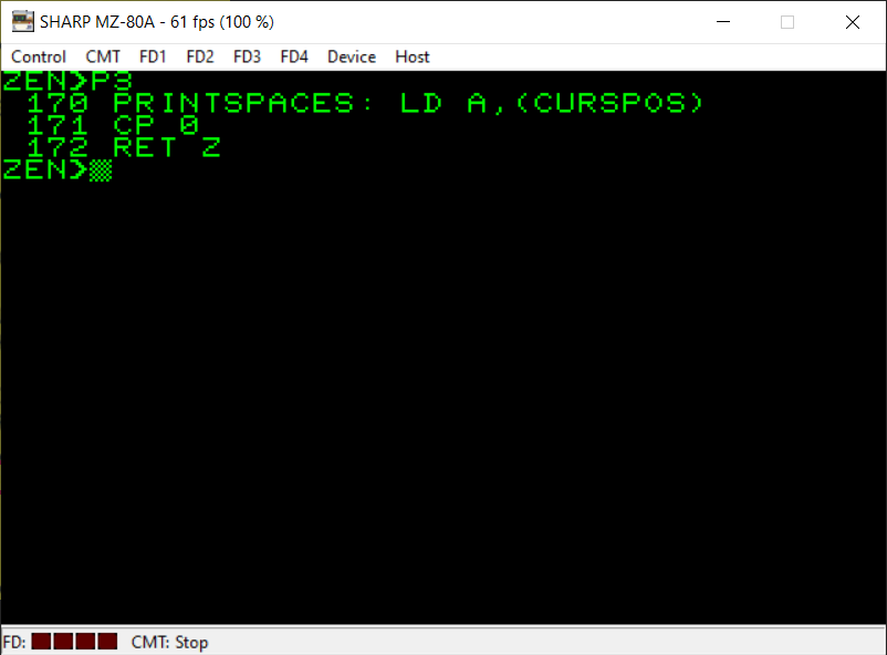
So that we’re able to create a loop we need to refer to the first instruction in the loop. I’ve given this first instruction in the loop the label ‘SPACELOOP’. On the MZ-80A there is a neat Monitor subroutine which will simply print one single Space character on the screen at the current cursor position. You can see this subroutine in the third screenshot above.
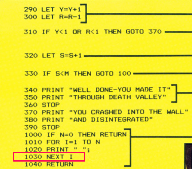
We can simply use the DJNZ instruction I mentioned previously as an equivalent of the BASIC ‘NEXT’ command. It will subtract 1 from the value currently in the B register, test whether it’s reached zero and jump back to the instruction at the label ‘SPACELOOP’ if it’s not.
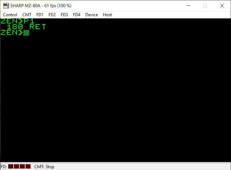
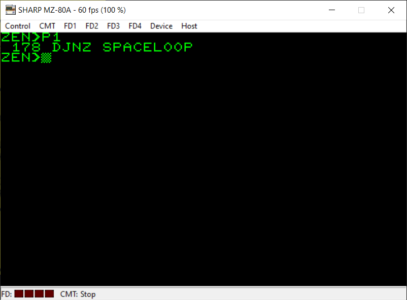
The machine code equivalent of the BASIC ‘RETURN’ is simply the ‘RET’ instruction. This one, without the Z, is unconditional. We will return back to the next instruction after the one which made the CALL to this subroutine.
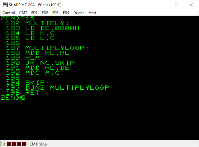
For reference, here is the subroutine I used which lets us multiply two numbers together. It is from the following website:
http://z80-heaven.wikidot.com/advanced-math#toc9
under the heading ‘DE_Times_A’.
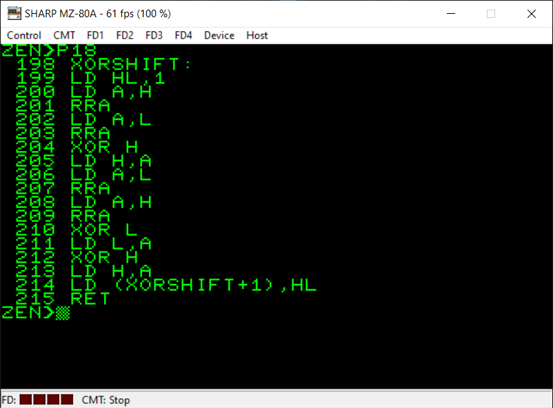
Here is the random number generator code I used which is from the following website:
https://wikiti.brandonw.net/index.php?title=Z80_Routines:Math:Random
under the ‘XOR Shift’ heading.
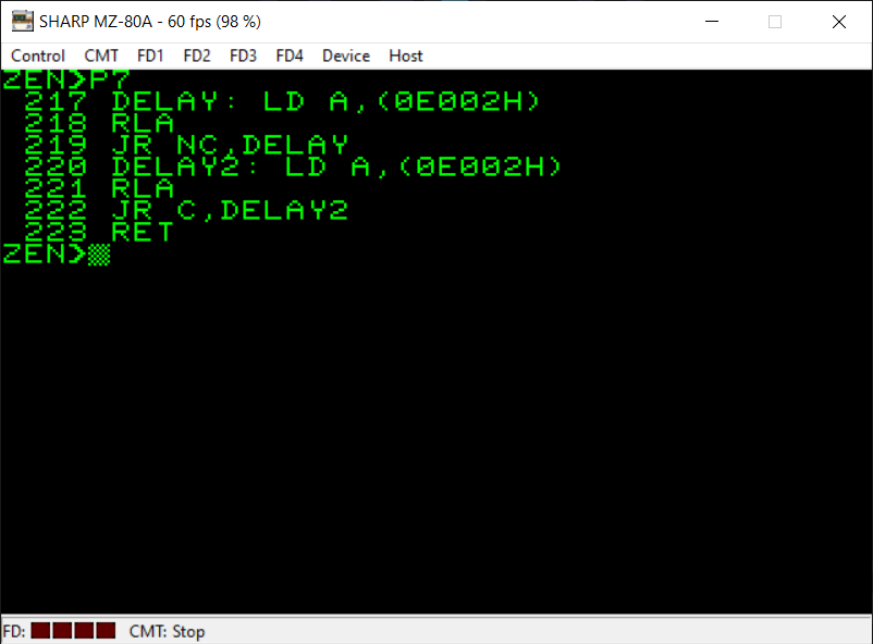

Here is the delay subroutine I created to slow the game down a bit for the player. It waits for the vertical blanking period of the MZ-80A’s display to begin (which happens every 60th of a second). I’ve also included a portion of the book “The MZ-80K and MZ-80A Explained” which also shows what this memory address ($E002) represents.
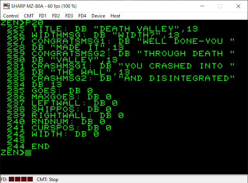
This final part of my assembly language conversion of Death Valley shows you all the variables I have used. As mentioned previously, you have to reserve some memory for all the variables you want to use.
To do this I use the ‘DB’ instruction. This actually isn’t a Z80 instruction but a command for the assembler itself. It tells the assembler to reserve a byte in memory (and you can set what that byte will be set to). You can also reserve several ASCII bytes in one go by enclosing them in speech marks (as seen for the variable ‘TITLE’ for instance).
The text strings always end with a carriage return (ASCII 13) byte. This is because the Monitor subroutine which prints text to the screen requires there to be an ASCII 13 character at the end of the text so that it can tell when to stop PRINTing.
Lastly, you’ll remember I mentioned you have to be careful about how you manage the memory. With that in mind, I have ensured that the ‘WIDTH’ variable is the very last variable I have reserved memory for. This is because it has two uses. Not only does it store the actual width of the play area but, you may remember, we’re also using it initially as the area in memory which stores the player’s input from the keyboard when they’re asked what width they would like. As they potentially could enter up to 80 characters if they wanted to with the Monitor input subroutine we’ve used this would cause a problem with our code if we reserved a single byte of memory at the beginning of our variables as it could end up overwriting memory locations reserved for other variables.
If you are going to use a variable length area of memory to store a string then ensure to put it at the end of your program.
The final instruction, ‘END’, is also not a Z80 instruction but a command for my assembler. My particular assembler (ZEN by Avalon Software) requires any program you write to end with the ‘END’ command so it knows where your program finishes.
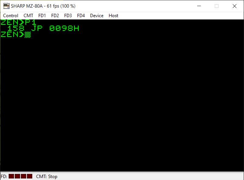
Finally, here is the video showing the machine code version of Death Valley running 🙂
